Charts and Supplemental Materials

Discover what ATC is telling you and how to reply with the information in this book here:
https://www.faa.gov/air_traffic/publications/media/pcg_basic_with_change_1_2_and_3_dtd_11-3-22.pdf
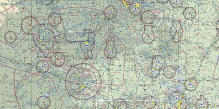
Get the digital version of any current VFR sectional here: https://www.faa.gov/air_traffic/flight_info/aeronav/digital_products/vfr/
Get the digital version here: https://www.faa.gov/air_traffic/flight_info/aeronav/digital_products/dafd/
Get the digital version here: https://www.faa.gov/air_traffic/flight_info/aeronav/digital_products/dtpp/
The graphics provided here give an unobstructed view of the Class B design without any underlying topographic features. The primary airport, primary navaid, and ceilings and floors are shown. Graphics show useful reference points and data to include:
- Geographic coordinates at each Class B boundary intersection
- Magnetic fix radial/DME to NAVAIDs
- Distance of each straight-line Class B boundary segment
Get the digital version here: https://www.faa.gov/air_traffic/flight_info/aeronav/digital_products/ifr/
The Federal Aviation Administration (FAA) Minimum Vectoring Altitude (MVA) charts and Minimum IFR Altitude (MIA) charts are available here in PDF format for users to identify the sector designs and minimum altitudes on charts used by Air Traffic Control. These charts are geo-referenced but are not to be used for navigation.
The Coded Instrument Flight Procedures (CIFP) is a dataset modeled to the Airlines Electronic Engineering Committee (AEEC) Aeronautical Radio Incorporated (ARINC) Navigation System Data Base (NDB) international standard (ARINC 424). The CIFP data can be used to support both En route and Terminal GPS navigation. Currently, ARINC 424 version 18 is provided. Version 18 supports WAAS RNAV (GPS) Approaches. The CIFP is raw ARINC data. It will require additional processing before it can be loaded into an avionics system.
The CIFP is updated every 28 days.
The Digital Obstacle File (updated every 56 days) describes all known obstacles of interest to aviation users in the United States, with limited coverage of the Pacific, the Caribbean, Canada, and Mexico. The obstacles are assigned unique numerical identifiers; accuracy codes, and listed in order by state.
U.S. IFR/VFR Low Altitude Planning Charts is designed for preflight and enroute flight planning for IFR/VFR flights. The chart is printed front-East, back-West, with insets for the east coast from Washington, D.C. to Boston and on the west coast, the Los Angeles/San Diego area. Information includes the depiction of low altitude LF/MF and VHF airways and mileages, navigational facilities, airports, special use airspace areas, cities, time zones, major drainage, a directory of airports with their airspace classification and a mileage table showing great circle distances between major airports, 40 x 36 inches. Revised every 56 days.
Gulf of Mexico and Caribbean Planning Charts is a VFR planning chart on the reverse side of Puerto Rico-Virgin Islands VFR Terminal Area Chart. Information shown includes mileages between airports of entry, a selection of special use airspace and a directory of airports with their available facilities and services, 60x20 inches folded to 5x10 inches. Revised every 56 days.
VFR Flyway Planning Charts are printed on the reverse sides of the Atlanta, Baltimore-Washington, Charlotte, Chicago, Cincinnati, Dallas-Ft. Worth, Denver/Colorado Springs, Detroit, Houston, Las Vegas, Los Angeles, Miami, Orlando, New Orleans, Phoenix, St. Louis, Salt Lake City, San Diego, San Francisco and Seattle Terminal Area Charts (TACs). The scale of these charts is 1:250,000, with area of coverage the same as the associated TACs. Flyway Planning Charts depict flight paths and altitudes recommended for use to by-pass areas heavily traversed by large turbine-powered aircraft. Ground references on these charts provide a guide for visual orientation. VFR Flyway Planning charts are designed for use in conjunction with TACs and are not to be used for navigation.
U.S. VFR Wall Planning Chart is designed for VFR preflight planning and provides aeronautical and topographic information of the conterminous U.S. The aeronautical information includes airports, radio aids to navigation, Class B airspace and special use airspace. The topographic information includes city tint, populated places, principal roads, drainage patterns and shaded relief. This chart, 59x36 inches flat, is updated annually.
Alaska VFR Wall Planning Chart is designed for VFR preflight planning and chart selection. It includes aeronautical and topographic information of the state of Alaska. The aeronautical information includes public and military airports; radio aids to navigation; and Class B, Class C, TRSA and special-use airspace. The topographic information includes city tint, populated places, principal roads, and shaded relief. The one sided chart is 58.5 x 40.75 inches and is designed for wall mounting. Chart is revised annually.

